As usual bridge activities since 1st January 2018 have been mainly about doing visual inspections of all of our structures, and planning projects for later in the year. Alastair Watson has done these visual inspections and produced reports with photographs for over 3 years since the restricted mobility of our structures engineer made it very difficult for him to continue with them.
During January 18, we carried out strike damage repairs to Bridge 1 at Broadway, which were entirely
paid for by insurers Aviva. Damage caused to some of the steel on the Up side
(above the eastbound lane) had required us to impose a 12T weight limit on that
half of the bridge, just when we were trying to lay track into Broadway station! More details of the repairs were included in
Blogs earlier this year.

At the same time as
these repairs, we fitted “LOW BRIDGE” signs on both sides of the bridge as can
be seen here.
Despite these signs, which have large letters
600mm high, the bridge has since suffered another 5 known very minor strikes, the last
being on 1st May 18. These strikes have only caused minor paint
damage and buckled the wasp stripe on the west side, north section. The lorry
owner’s insurers (AXA) have just agreed to pay for the repairs. These will be
done in conjunction with the Collision Protection Beam works (see below).
Another “last
minute” project, which was done in July, is at Bridge 38 near Bishops Cleeve,
which has a Public footpath passing beneath it. This area has, for years, been
a “den” for youths drinking, and causing damage to fencing, bridge brickwork, and
also spraying many lots of graffiti all over the bridge brickwork.

It was
subjected to a very severe graffiti vandalism attack earlier this year. We believe that these youths had also set fire to our Greenmech
vegetation clearing machine a couple of years ago where it was parked under the
next bridge north. It was a total loss.
 |
| New anti vandal walkway under bridge 38 |
Stones were also recently
thrown at our Drainage gang here, and broken bottles of alcohol were found up on the trackbed. Consequently we have decided to install palisade fencing, to prevent unauthorised track access, to
reduce the area where the youths gathered and to stop them being able to reach
the walls to do any more “artwork”!! Hopefully without a nice sheltered place
in which to congregate they will stop causing us any more trouble.
The fencing work
was done by Gloucester firm Greenfields and was completed in about a week.
The work programme
for the rest of the year is just starting, basic details being as follows:-
1. BRIDGE 1 - INSTALLATION OF A COLLISION PROTECTION
BEAM SYSTEM
The design was
completed by Engineers Halcrow (now part of Jacobs) early this year and tenders
were obtained. Then an order was placed on 25th May with Nu-weld
Engineering Services of Halesowen. Fabrication has been in progress ever since,
followed by hot dip galvanising and then painting to match the bridge steelwork.
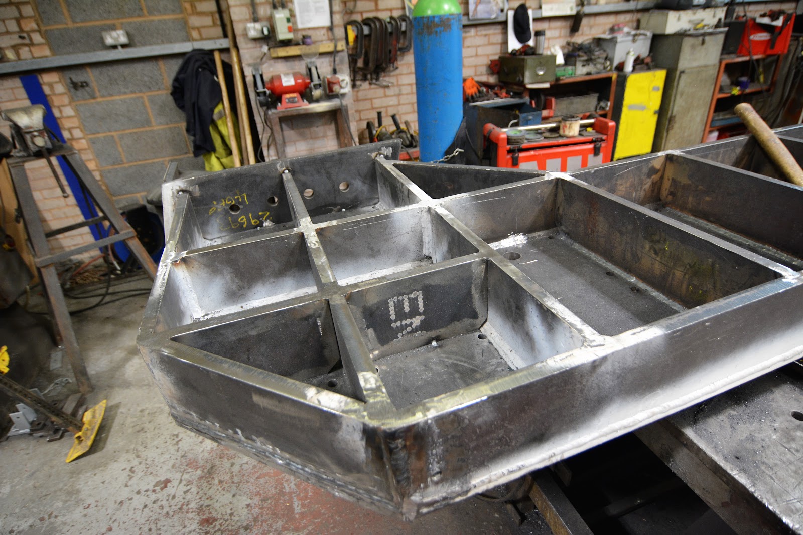 |
| Channel section during manufacture |
Here is one of the substantial channel sections, seen during manufacture at Halesowen
 |
| Anchor bolts |
 |
| A completed channel section |
The system comprises
two heavily welded steel channel section beams which bolt to the upper part of
the abutment brickwork. The beams are in two halves to simplify erection and
fixing. Each beam is fixed to the brickwork with 40 No. 30mm diam resin anchor
bolts, set 650mm into the brickwork.
The actual Collision Protection Beams are
made from 400mm square hollow box sections which are filled with concrete
before installation. These will weigh app. 5.5T each when full of concrete and
are designed to take an impact from a lorry travelling at 45 MPH. They are
positioned app 200mm in front of the bridge steelwork and should deflect no
more than 150mm if such an incident happened. These box beams span the road and
sit on the upstanding brackets you can see on the ends of the abutment beams.

This picture shows the upstanding brackets on the end of the abutment beams. The holes are for the resin anchor bolts which fix them to the abutment behind.

Delivery and
installation started on Monday 3rd September 2018. Each abutment beam
will take about two weeks to install, and a half-road, traffic light controlled
closure will be in place for this work.

The installation of the two
cross beams will take place when the abutment beams are completed and grouting
against the uneven brickwork behind is completed. Yesterday
the two half-beams for the north abutment were unloaded, and temporary Mabey support
columns to take the weight whilst the wall is being drilled were installed.

Here is the north side abutment beam unloaded and ready for installation, to be temporarily held in place by the Mabey support columns.
The completed
installation will look fairly similar to the system installed under the NR main
line in Hyde Lane, Cheltenham:

This bridge has a clearance of 3.9m, less than our bridge at Broadway. As can be seen it has already had plenty of use.
2.
BRIDGE 12 – STANWAY VIADUCT – DETAILED INSPECTION OF
THE ENTIRE STRUCTURE
BRIDGE 8 – B4632 SKEW BRIDGE, STANTON
BRIDGE 7 – STANTON FIELDS PRIVATE ROAD
As part of the
requirement to carry out a Principal Inspection (i.e. a detailed, close up
inspection), of all of our Bridges on a 6-year rolling cycle basis, the time
has come for Stanway viaduct to be done. The work will be carried out by a team from
Bridgeway Consulting Ltd., who are bridge inspection specialists. The structure
has 15 arches, each spanning approximately 12.6m, and rises to approximately 13m high to track level
above the fields below.
The two arches at
each end have sloping embankments under them and one span is over a small
stream. Consequently only 10 arches can be done using a traditional Cherry
picker and the remaining 5 will have to be done using aerial rope workers.
Inspection of the 10 arches will start later this month, as it will not
interfere with train operations. It should take less than a week. However the
rope work requires the main support cables to be attached to the track and so
this work will have to be done in November when no trains are running. Again
about a week’s work will be involved.
It is hoped that Bridges 7 & 8 can
also be done in September, so that the same cherry picker can be used. These
two can be done in a day and we do have an odd train-free day in September to
slot it in.
There are also
problems with ground slippage at each of the 4 end corners of the viaduct.
 |
| A corner of Stanway viaduct after lineside clearance, and with earlier gabion repair |
 |
| Failure of temporary wall |
A temporary solution using redundant concrete sleepers was installed a few years ago, but as can be seen, these are now leaning over and need to be replaced with a more substantial long term solution.
 |
| Concrete sleeper repair |
A similar king – post scheme will be designed soon but requires some soil sampling to be done first. Our Lineside clearance team have been doing a great job of clearing vegetation all around this structure to make the viaduct inspection simpler, and the king-post design and ground investigation work much clearer.
3. BRIDGE 9 – STANTON AQUEDUCT AND PUBLIC FOOTPATH
This is a 3-span
structure formed from a steel box shaped channel, supported on two trackside
brick piers and two brick or concrete abutments. A public footpath runs along the top of the channel.
 |
| General view of the aqueduct from below |

The box leaks and is badly corroded with the steel thickness reduced to approximately half of its original thickness.
The leaking water here is softening the foundations of the abutment.

This view from above shows the Cotswolds entrance to the channel, and the footpath.
 |
| Level view of the aqueduct. It was constructed by E. Finch of Chepstow in 1904. |
Bits of scale have been falling off and the wooden walkway is very
unstable, and so it has had to be closed. The entry structure on the Cotswold
side leaks and water is softening the ground beneath the supporting brick
abutment. We have appointed contractor Stepnell and work will start on 1st
November and will take about 6 weeks.
The photographs in the Halesowen factory were taken by John Fancote, a welcome new volunteer recruit for the bridges team. John has spent 41 years working indirectly for Network Rail, mainly as an examining engineer for Amey.
Other photographs and the blog report itself are by John Balderstone, GWSR Structures Engineer.
Would it not be feasible to attach accelerometers to the bridges (and now the deflection beams) to detect the lateral movement caused by an impact, that would automatically signal back to a "control centre" that would be able to give near instant notification of a bridge strike?
ReplyDeleteThere are additional options for the crash protection beam, but the beam itself is already very expensive and we must try to limit expenditure.
DeleteWe will see how effective the beam is, and then decide what additional measures are needed, if any.
The main advantage of the Crash Protection Beams, other than preventing damage to the main bridge, is that even if they have been hit, trains can still run. This would remove the urgency of inspecting the bridge after an incident and before trains can resume running.
DeleteI'm not talking expensive here in fact very cheap to deploy Lora based detector that could be used to monitor multiple things out on the railway and either give event or regular reporting. https://www.thethingsnetwork.org/
DeleteWhat a wonderful and lengthy report! A huge 'thank you' to Mr. Balderstone for all the time and effort to prepare it, and to Jo for the work involved to post it! It is much appreciated!
ReplyDeleteOne quick question: will the steel on the aqueduct be replaced, or merely repaired? (Not that I would have any problem with the latter, I'm sure the work will be done to the highest standard, as is usual on the GWSR! Just curious. And I'm so happy to see all the infrastructure being so well maintained!)
Noel
The corrosion is so variable and extensive, reducing the steel plate thicknesses by up to 50% and causing dozens of short lengths of the 1/2" thick horizontal steel angle leg supporting the timber walkway completely, that there is no practical way in which this could be repaired. Total replacement of the 34M long, 3-span structure is the only option.
DeleteThanks for the quick follow-up! I've got my fingers crossed they won't turn up too many unknowns when work starts!
DeleteNoel
Will there be any attempt to make it a heritage replacement or are we looking at a lump of concrete?
DeleteSad to lose a classic structure but do completely understand why it has to be done.
The aqueduct itself will look almost identical, being a 500mm square box as opposed to a 457 x 457 open topped channel. The handrails will be similar but higher to meet current safety requirements. The sides above the track will be filled with open mesh to stop anything falling onto the trains. The brick piers and west abutment will remain, and a new concrete abutment will be built on the east side.
DeleteExcellent detail, thank you John.
DeleteWould it be possible to line the new concrete abutment with blue bricks to match the remaining structures?
DeleteI am interested that you have chosen a box section for the aqueduct rather than an open topped channel. I wonder if the old channel ever over-topped after heavy rainfall, dumping the excess water on the track bed? Presumably a closed box would cause the inlet side to back up, meaning excess water would go over the abutment. Perhaps this is such a rare occurrence that it need not be considered? Alternatively, some sort of overflow weir could be incorporated at the inlet with a pipe down to the track drainage. Or maybe just cut some holes near the top of the box so that it overflows onto the trackbed? Always curious as to why design decisions are made!!
ReplyDeleteTrevor - The bank seat on the west side was re-built in concrete back in 2002, before I was involved, so we will be matching that. There is little of this structure visible, anyway, especially when the vegetation gets going!
ReplyDeletePeter - We have never had any problems with the channel overflowing and it is completely dry for much of the year. The existing open-top channel lacks lateral stability in compression and so the box is a much stronger replacement. It also has the advantage that it has 22% extra capacity when full, but that is unlikely to happen. It will hold about 6% extra at all intermediate water depths due to the small extra width.
Presumably the box-section of the structure will make it difficult to remove any blockages within. Is there an intention to install a grid across the entrance end to prevent vegetation, etc being washed in?
DeleteGreat news that the Collision Protection Beams for the bridge at Broadway, are now being installed.
ReplyDeleteThis is clearly the best solution and will, with all luck, protect the bridge and allow the trains continuous use of Broadway Station.
I always felt with the 'unguarded' bridge, further bridge strikes by high lorries and vehicles could cause serious disruption to the timetable.
All being well, that potential problem will be gone in a few weeks time.
We have about 60 culverts passing under our embankments and only the odd one has any form of grid. They also have the disadvantage in that leaves tend to build up on the gratings and cause a worse blockage! We will not be putting one in here.
ReplyDeleteMark - Yes we are all hoping that we do not get a strike before it is completed. The huge advantage should be that if the CPB does get struck no damage should be caused to the actual bridge steelwork. Consequently - no train disruption.
John,
DeleteThanks for the comment. Fingers crossed that NO further strikes occur during the installation, BUT with the traffic lights there at the moment, ‘in situ’, they will hopefully deter that possibility.
Events happening like this, are a nightmare for everybody concerned!
Ely Standard: Britain's most bashed bridge is in Ely
https://www.youtube.com/watch?v=mNZUgkZ4BP8
The Definitive 11Foot8 Bridge Crash Compilation
https://www.youtube.com/watch?v=USu8vT_tfdw
Very hungry canopener bridge defeats fancy, new warning system
https://www.youtube.com/watch?v=iQfSvIgIs_M
Mark